A while ago, my Triton electric shower started cycling onto ‘low-pressure’ mode every 10-15 seconds. This meant that the water would flip between hot and freezing cold. Not pleasant. A bit of internet searching revealed that this is a fault in a safety sub-circuit, which is ordinarily supposed to turn to cold water when it thinks that you are at risk of getting burnt by the water.
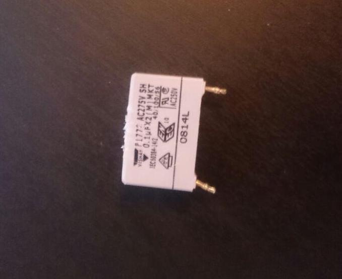
The solution to this problem came from this handy thread. Apparently, it is caused by a faulty C3 capacitor on the main PCB. That, in itself, is a pretty straightforward electronics job, and much cheaper than calling an engineer, who would probably just replace the whole board and charge a bomb to do it. The capacitor is a 0.1 micro-Farad version, available from Maplin in the UK here for less than £1 at the time of writing.
In what follows, I will present a simple guide on how to do this replacement yourself. My particular Triton shower was a 100xr, but it appears as if the circuitry is similar in most Triton showers.
Things you will need
- A Phillips head screwdriver
- Soldering iron and solder (a solder sucker is also useful but not essential)
- Stanley knife or equivalent (to cut through plastic spade cover)
- Flat screwdriver or similar (to prise open the spade)
- Pliers or wire crimpers (to take out the old capacitor and crimp the spades)
- Patience!
The process
Step 1 – Turn off the mains!
This is important! You are dealing with live wiring, so be very careful to switch off all power to the shower before proceeding.
Step 2 – Open the front cover
Your shower may vary in terms of where the screws are located. Mine had 2 on the top edge and one on the bottom next to the pipes.

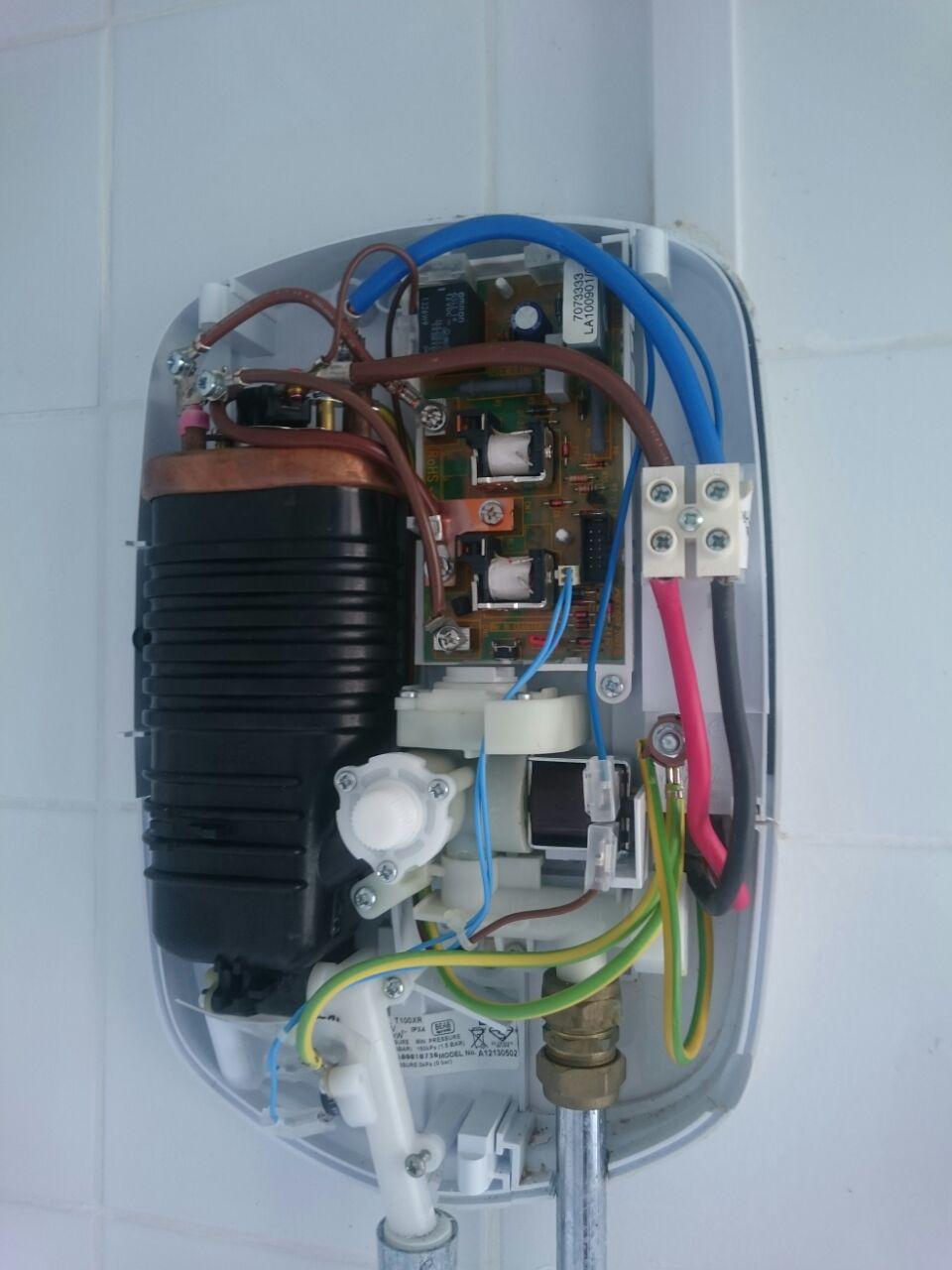
There is one connector which joins the front panel controls to the PCB, which you can just unplug by hand. I would recommend taking a photo of the insides like I’ve done here so that you know where everything goes when you hook the wires back up.
Step 3 – Take out the PCB
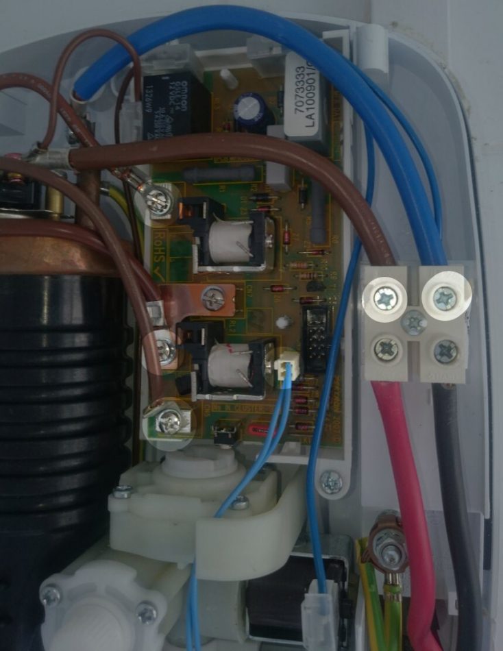
This is the most frustrating part of the process. Firstly, unplug the blue connector in the centre by hand. Then, you want to unscrew the wire terminals that are attached to (or block) the PCB. I’ve highlighted all of these points below.
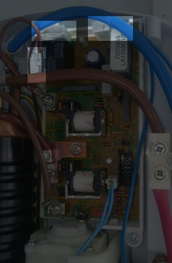
Next comes the awkward part. There are 3 terminals on the PCB highlighted below that are connected using right-angled spades. In my case, they were also covered with a plastic protective casing. Unfortunately, there was no way for me to remove these without cutting them off. It’s a little awkward, but you can do it with a Stanley knife. Be careful not to cut yourself or damage the circuit board.
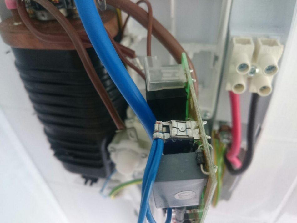
The last job before you can remove the PCB is to undo the spade connectors underneath the plastic covers that you just cut off. You should be able to wedge a flat screwdriver or a knife in there to bend the arms open, which will allow you to pop the wire off the metal rectangular terminal.
That’s the painful part over! The PCB is just secured by plastic tabs in the casing, so you just need a flat screwdriver to push down the tabs and pull out the board.
Step 4 – Replace the capacitor
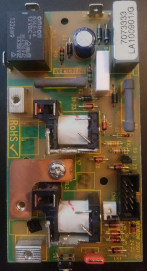
I’ve highlighted the C3 capacitor – it’s the off-white rectangle near the top. Don’t worry, it also says ‘C3’ on the board next to it, in case your PCB is slightly different. I don’t have photos of the back of the PCB, unfortunately, but there are guides on soldering around the internet if you haven’t done any before. It’s pretty simple in this case. Heat up the solder around the two pins of the capacitor, and remove the capacitor from the board. You may need to use pliers or tweezers, since it will get quite hot to the touch. It’s also useful to suck up any additional solder if you can.
Place the new capacitor in the old one’s place, and solder the pins to the board. You might find it useful to have a tea towel to place underneath the board in order to keep the capacitor in place whilst you solder it in. That’s it!
Step 5 – Put the board back in
Now the process is just the reverse of what we did before. Snap the board in place, crimp the spade connectors back around the terminals (you can put on new plastic covers to replace the old ones if you like, but I didn’t bother in case future repairs are required). Use crimpers if you have them, otherwise pliers should do.
Screw all the wires back in place, and plug the blue connector in. Get your front cover, and plug the controls into the PCB before screwing the cover back on.
Step 6 – Turn the electricity back on and test
Hopefully, things should work as normal, and you can stand under your shower without having to dodge the water every 10 seconds. According to the thread I found at the beginning of this post, it seems as though this solution worked for the majority of people with the ‘hot-cold’ problem.
Total cost = 89p for the capacitor, and a couple of hours worth of fiddling with screws. Hopefully, this guide should help you do it far quicker than it took me.
Can I bypass this bord completely?